
What Is a Motor Braking Resistor and How Does It Work?

When a conveyor stops with a heavy load, the motor may continue producing energy as it slows down. That energy needs somewhere to go. A Motor Braking Resistor provides a controlled path for dissipating it as heat, helping a variable-frequency drive manage deceleration and limit excessive DC-bus voltage. The resistor does not stop the motor by itself. The drive’s braking circuit controls when energy flows through it.

The effect is practical and visible: during repeated stops, the resistor can become hot, so its placement, ventilation, and temperature rating matter. Resistance, power rating, braking duration, and stopping frequency all influence selection. A unit suited to occasional stops may overheat on a fast-cycling machine. Not a magic fix. The drive’s manual and the equipment manufacturer’s specifications should guide installation and sizing; operating conditions can change the answer. It is also worth checking whether the application needs a braking resistor at all, since some drives handle slowing without one. That detail is easy to overlook. Understanding how the resistor works makes it easier to assess performance, recognize heat-related risks, and discuss the right setup with a qualified technician.
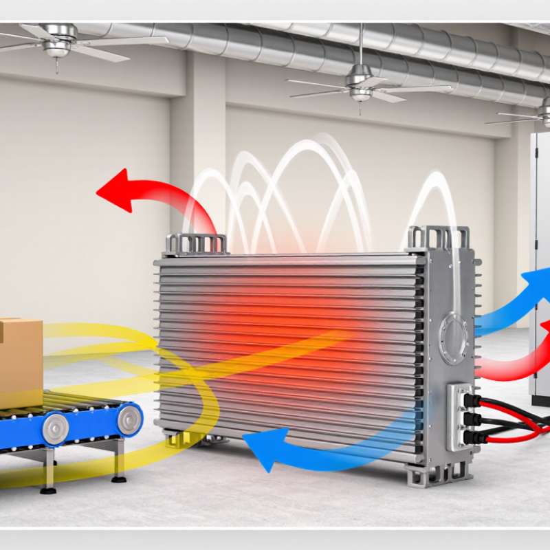
What Is a Motor Braking Resistor and How Does It Work?

Define a Motor Braking Resistor: Converting Regenerative Energy into Heat

A motor braking resistor is an electrical component that turns excess regenerative energy into heat. When a motor slows a moving load, it can act like a generator. The resulting energy flows back toward the drive’s DC bus instead of disappearing. That is the basic idea.

If the DC bus voltage rises above a set level, a braking circuit connects the resistor. Current then passes through its resistive element, often a metal grid or wire-wound assembly. The energy becomes heat, which the resistor releases into the surrounding air. A lift lowering a heavy platform or a conveyor stopping a full load can create this condition. The resistor helps control bus voltage and allows quicker, more predictable deceleration. It does not physically stop the motor by itself.

Heat matters. A resistor that is too small, poorly ventilated, or used too often may overheat. Engineers consider resistance, pulse energy, braking frequency, and cooling conditions when selecting one. The cabinet can feel warm after repeated stops; that warmth is expected, but excessive temperature is not. The simplified explanation can hide variations between drive systems, so installation limits and thermal protection still need careful review. Regenerative energy is being dissipated, not recovered for reuse.


What Is a Motor Braking Resistor and How Does It Work?

A motor braking resistor converts regenerative electrical energy into heat during deceleration. The drive sends energy produced by the motor to the resistor, where it is dissipated rather than returned to the power supply.

Illustrative example: the bars show energy dissipated as heat in each 0.5-second interval of a 5-second braking event, totaling 12.5 kJ. Actual energy depends on the motor, load, speed, and braking profile.

Follow the VFD Braking Path: Motor → DC Bus → Chopper → Resistor

When a load slows, the motor may act like a generator. A descending lift or rapidly decelerating conveyor can send energy back toward the variable-frequency drive (VFD). The motor is the starting point, but the braking resistor does not connect directly to it.

Follow the path: motor, DC bus, chopper, resistor.

The returning energy raises the DC bus voltage inside the drive. If that voltage reaches a set threshold, a braking chopper switches on and routes current through the resistor. The resistor converts electrical energy into heat, which is why its enclosure needs clear airflow and must stay away from heat-sensitive parts. The chopper switches rapidly. The resistor gets warm.

In commissioning, technicians can observe deceleration time, bus voltage, and resistor temperature to check whether braking behaves as expected. A resistor that is too small may overheat; one that is incorrectly matched may not control bus voltage adequately. Not the whole story. Repeated stops, load inertia, and the drive’s braking duty all affect selection, so a brief test under light load cannot prove the setup is safe for every cycle. A small wiring or ventilation detail can change the result.

Estimate Braking Energy with E = ½Jω² and Resistor Power with P = V²/R

A motor braking resistor helps absorb electrical energy when a motor slows down. Estimate the rotating load’s braking energy with E = ½Jω², where J is inertia in kg·m² and ω is speed in radians per second. The result is in joules. For example, a heavy flywheel spinning quickly can produce a substantial energy pulse. Include inertia reflected through the drivetrain, not just the motor rotor. A rough estimate can miss changing loads and friction, so treat it as a starting point.

Resistor heating depends on the voltage across it. Use P = V²/R to estimate instantaneous power: a higher voltage or lower resistance increases dissipation. This does not tell you whether the resistor can survive a complete stop. Check pulse-energy limits, cooling, and how often braking repeats. Average power also matters; frequent stops can heat a resistor even when each individual pulse seems manageable. The drive’s braking circuit and measured DC-bus voltage affect the actual conditions.

Tips: Record the load, speed, stop time, and braking frequency. Units matter. Compare calculated energy with the resistor’s pulse rating, then verify temperatures during real operation. Leave a safety margin; estimates are imperfect.

Check Typical DC-Bus Voltage: About 540–565 V for a 400 V-Class Drive

A motor braking resistor gives regenerated energy a controlled place to go when a motor slows down or lowers a load. During deceleration, the motor can act like a generator, sending energy back to the drive’s DC bus. If bus voltage rises too far, the drive’s braking circuit switches current through the resistor. The resistor turns that energy into heat. Briefly, it is a heat-making component.

For a 400 V-class drive, a DC bus around 540–565 V is a useful typical range under normal supply conditions. A 400 V three-phase input has a peak voltage near 566 V after rectification, though actual readings vary with supply voltage, load, and ripple. Not a fixed value. A bus reading below this range does not automatically mean a fault, and a higher reading during braking may be brief. Check the drive documentation and measure only with suitable equipment and safe procedures; the bus can remain charged after power is removed.

When commissioning or troubleshooting, observe the bus during a controlled stop. A sharp voltage rise can suggest that braking energy is not being dissipated effectively, but resistor wiring, drive settings, and load inertia also matter. The numbers are not perfectly tidy. A handheld meter may miss short peaks, so the displayed value can tell only part of the story. Don’t select a resistor from bus voltage alone; verify resistance, pulse-energy capacity, and duty cycle against the drive’s specified limits.

Size for Peak Power and Duty Cycle, Then Verify IEC 61800-5-1 Safety Requirements

A motor braking resistor converts regenerated electrical energy into heat when a motor slows down. Without a suitable energy path, the drive’s DC bus voltage can rise and trigger a fault. You may notice this during repeated stops, lowering a suspended load, or a fast deceleration on a conveyor. The resistor does not stop the motor by itself; the drive controls braking.

Size it for peak power and duty cycle, not just the motor’s rated power. Peak power covers the brief braking event, while duty cycle describes how often and how long those events occur. Use the drive manufacturer’s calculations and the motor’s inertia, speed change, stopping time, and operating pattern. Check resistance limits, pulse-energy capacity, and average thermal load. Leave margin. A spreadsheet can look precise, yet real stop times may differ from the assumptions. Measure the actual cycle where practical, then reassess.

Verify the complete drive-and-resistor installation against the applicable IEC 61800-5-1 requirements and the drive documentation. Pay attention to thermal protection, enclosure temperature, wiring clearances, protective bonding, and what happens if braking control fails. Mount the resistor where hot surfaces cannot contact cables or combustible materials, and allow airflow around it. It gets hot. Do not treat a resistor’s wattage label as proof of system safety; qualified personnel should review the installation and its fault protections.

REQUEST A QUOTE

Menu
[all-fields]