
How to Choose the Right VFD PCB Board?
Choosing the right Vfd Pcb Board can determine whether a motor system runs smoothly or fails under pressure. The board is not merely a replacement part. It controls signals, protects switching components, and communicates with the drive’s control system.
A practical selection begins with the original drive model, rated input voltage, motor current, and control architecture. Check the manufacturer’s datasheet carefully. A board designed for a 400 V industrial drive may not suit a smaller 230 V unit. Fit is not enough. Connector position, firmware version, heat tolerance, and communication protocols also require confirmation.
Small details matter.
In real maintenance environments, technicians often inspect burned terminals, cracked solder joints, and swollen capacitors before ordering a replacement. These clues may reveal a deeper problem, such as poor ventilation, unstable power, or excessive motor loading. Replacing the Vfd Pcb Board alone may not solve repeated failures. That point is easy to overlook.
Reliable suppliers should provide traceable specifications, inspection records, warranty terms, and technical support. Independent testing can also confirm insulation quality, signal accuracy, and performance at elevated temperatures. Avoid choosing only by price. A low-cost board with uncertain components may create longer downtime and higher repair costs.
There is no universal board for every application. The best choice balances compatibility, reliability, serviceability, and long-term operating conditions. However, selection decisions are not always perfect. Field measurements can be incomplete, and older drives may lack clear documentation. A careful comparison, supported by qualified technicians, reduces uncertainty before installation.
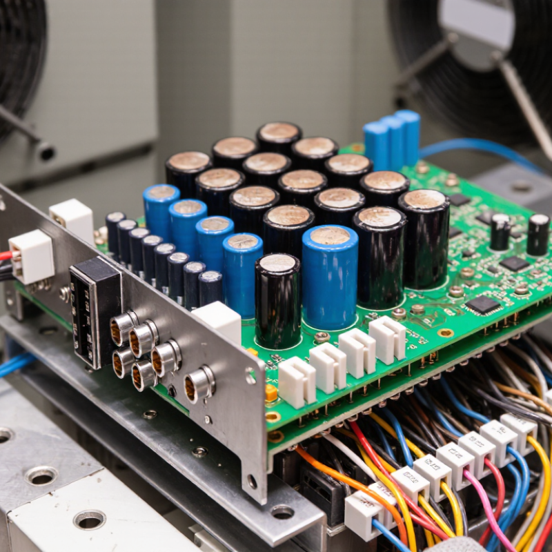
Understanding the Role and Types of VFD PCB Boards
How to Choose the Right VFD PCB Board?
A VFD PCB board acts as the drive’s control center. It reads speed commands, measures current, and controls switching signals. Some boards manage logic only, while others combine control, sensing, and communication circuits. This distinction matters during replacement. A board can fit physically yet fail electrically. The International Energy Agency reports that electric motor systems consume about 53% of global electricity. Efficient drive control therefore affects both machine performance and operating cost (IEA, Energy Efficiency 2016).
Common VFD PCB types include control boards, gate-driver boards, power-interface boards, and communication boards. Control boards process feedback from encoders, temperature sensors, and current transformers. Gate-driver boards operate switching devices with tightly timed pulses. Power-interface boards handle high-voltage measurement and protection. Communication boards connect the drive with automation networks. In practice, these functions may share one assembly. That makes troubleshooting less obvious.
Selection should begin with voltage class, motor current, overload duty, and enclosure conditions. Check connector positions, firmware compatibility, isolation ratings, and cooling requirements. IEC 61800-5-1 addresses electrical safety, while IEC 61800-3 covers electromagnetic compatibility for adjustable-speed systems. Field inspections often reveal a neglected detail: dust on cooling channels can raise PCB temperature quickly. A replacement should also match the original sensing range and gate-drive timing. A lower-cost board may work initially, but incomplete documentation remains a serious risk. Even experienced technicians can overlook aging capacitors, loose terminals, or moisture marks during a hurried inspection.
How to Choose the Right VFD PCB Board? - Understanding the Role and Types of VFD PCB Boards
| VFD PCB Board Type | Primary Role | Typical Signals or Components | Typical Operating Considerations | Best Selection Criteria | Common Failure Symptoms |
|---|---|---|---|---|---|
| Main Control PCB | Runs the inverter control logic, speed regulation, acceleration and deceleration profiles, and protection algorithms. | Microcontroller or processor, memory, analog inputs, digital inputs, PWM outputs, current feedback, and voltage feedback. | Requires stable low-voltage power, correct firmware compatibility, adequate grounding, and protection from electrical noise. | Match the inverter series, rated input and output configuration, control method, firmware version, connector layout, and communication requirements. | No display, incorrect speed control, unexpected trips, loss of parameter memory, or failure to start. |
| Gate Driver PCB | Converts low-power control pulses into properly timed gate-drive signals for the inverter switching devices. | Isolation circuits, gate-drive transformers or isolators, bootstrap circuits, desaturation protection, and gate resistors. | Must provide electrical isolation, correct gate voltage, suitable switching timing, and protection against short circuits. | Verify compatibility with the installed IGBT or power module, switching frequency, isolation rating, connector position, and protection scheme. | Overcurrent trips, phase loss, abnormal motor noise, immediate shutdown, or damaged switching devices. |
| Power Interface PCB | Routes and monitors connections between the rectifier, DC link, braking circuit, inverter bridge, and control electronics. | Bus-voltage sensing, current shunts or sensors, pre-charge interface, relay drivers, braking resistor interface, and terminal connectors. | Must withstand the applicable voltage, current, temperature, vibration, and clearance requirements of the drive. | Check voltage class, current rating, creepage and clearance, terminal arrangement, sensor type, and braking hardware compatibility. | DC-bus overvoltage or undervoltage faults, pre-charge failure, inaccurate current readings, or braking malfunction. |
| Power Supply PCB | Generates regulated low-voltage rails for the control board, gate drivers, sensors, fans, and interface circuits. | Switch-mode supply, transformers, rectifiers, voltage regulators, fuses, feedback circuits, and protection components. | Output voltage stability, isolation, thermal performance, and adequate protection against surges are essential. | Match input range, output rails, power capacity, isolation requirements, connector pinout, and mounting dimensions. | Blank display, repeated resets, communication loss, fan failure, or multiple low-voltage fault codes. |
| Interface and Keypad PCB | Provides local operation, parameter entry, status indication, and fault-code display. | Push buttons, membrane keypad, display module, indicator LEDs, potentiometer interface, and serial connection. | Needs mechanical compatibility, clear display visibility, reliable connector contact, and suitable enclosure protection. | Confirm display type, keypad layout, cable length, connector orientation, enclosure fit, and supported parameter functions. | Unresponsive keys, missing segments, intermittent display, or inability to access parameters. |
| Communication PCB | Connects the VFD to a PLC, industrial controller, supervisory system, or networked automation system. | Serial transceivers, Ethernet interface circuits, isolated communication channels, termination components, and status LEDs. | Requires correct protocol settings, cable shielding, termination, isolation, and electromagnetic compatibility practices. | Match the communication protocol, connector type, baud rate or network speed, isolation level, addressing method, and software support. | Communication timeout, corrupted data, intermittent connection, or inability to read and write parameters. |
| Cooling and Protection PCB | Controls cooling fans and monitors thermal, airflow, door, and other protective conditions. | Fan drivers, temperature sensors, thermal switches, airflow inputs, relays, and alarm circuits. | Performance depends on correct sensor characteristics, clean airflow, fan voltage, and ambient temperature limits. | Check sensor type, fan voltage, connector arrangement, alarm logic, environmental rating, and physical location. | Overtemperature alarms, fan-not-running faults, nuisance trips, or reduced output capability. |