
How to Choose a Bi Telecentric Lens?
Choosing a bi telecentric lens begins with one practical question: what must remain accurate?
In dimensional inspection, a small part may sit slightly closer to the camera. A conventional lens changes its apparent size. A bi telecentric lens helps preserve consistent magnification from both object and image sides. That stability can protect measurements of holes, edges, pins, and molded profiles.
It is not magic.
Optical design expert Dr. David Shafer has described telecentric imaging as “a measurement tool with trade-offs.” That reminder matters. A telecentric lens can improve geometric reliability, yet it may require more space, controlled lighting, and careful alignment. A larger lens diameter may also raise cost.
Experienced engineers usually compare object-space telecentricity, image-space telecentricity, or true bi-telecentric performance. They check the required magnification, sensor format, working distance, depth of field, and distortion specification. A 0.5× lens may suit one inspection station, but fail when the camera sensor changes. Tiny errors become visible.
Look closely.
This guide, “How to Choose a Bi Telecentric Lens?”, follows the decisions made on a real inspection bench. It considers measurement tolerance, part movement, illumination, mounting clearance, and calibration practice. It also questions a common assumption: maximum telecentricity is not always the best purchase. Sometimes, a simpler lens delivers enough accuracy with easier integration. The correct choice depends on the application, not the product label alone.
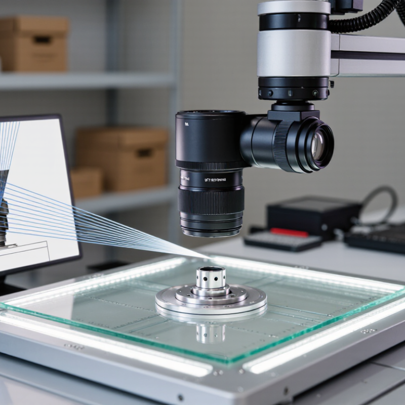
Define the Measurement Goals and Object-Space Requirements
Choosing a bi telecentric lens starts with the measurement goal, not the camera. Decide whether you need diameter, edge position, height, or surface-defect data. Each goal demands different contrast and resolution. In 2023, 541,302 industrial robots were installed worldwide, according to the International Federation of Robotics. Automated inspection is expanding, but speed cannot replace traceable accuracy.
Define the object-space requirements with measured values. Record the part’s field of view, working distance, largest height variation, and smallest feature. A telecentric lens should cover the full object without forcing the part near the image edge. Check depth of field carefully. A thick metal component may look sharp on one face and soft on another. Low distortion matters when dimensions are calculated from pixels. VDI/VDE 2634 recommends calibrated artefacts for testing optical measurement systems. Use one during validation, not only during installation.
Tips: Measure the actual part, not a simplified drawing. Leave clearance for lighting and fixturing. Test the lens with production materials, because reflective surfaces can expose weaknesses. A common mistake is choosing magnification first. Reconsider it if the sensor cannot resolve the smallest tolerance. The correct setup may require a larger field of view and better lighting, not more magnification. Even experienced engineers sometimes underestimate vibration, thermal drift, or imperfect alignment. Record those uncertainties before approving the measurement design.
How to Choose a Bi Telecentric Lens? - Define the Measurement Goals and Object-Space Requirements
| Measurement Goal | Typical Object | Recommended Field of View | Object-Space Requirement | Suggested Lens Characteristics | Important Selection Notes |
|---|---|---|---|---|---|
| Dimensional inspection of precision parts | Machined components, pins, holes, edges, and profiles | Part size plus approximately 10–20% margin | Stable working distance; controlled depth variation; measurable features must remain inside the telecentric region | High object-space telecentricity, low distortion, high resolving power, and sufficient image-circle coverage | Choose magnification from the required pixel resolution. Keep the field of view only as large as necessary to avoid sacrificing optical resolution. |
| Go/no-go inspection | Gaskets, molded parts, stamped components, and assembly features | Complete part outline with a small clearance margin | Repeatable part positioning; moderate object depth; consistent contrast between feature and background | Low distortion, generous depth of field, robust illumination compatibility, and adequate working distance | A slightly larger field of view can improve tolerance to placement errors, but excessive margin reduces the number of pixels available for each feature. |
| Measurement across varying heights | Stepped parts, connectors, housings, and components with uneven surfaces | Projected feature area plus the expected height-related positional shift | Object height range must be smaller than the usable telecentric depth and depth of field | Bi-telecentric design with specified telecentric depth, low magnification variation, and adequate aperture control | Bi-telecentricity reduces sensitivity to object and sensor-side displacement, but it does not eliminate focus limits or perspective errors caused by features outside the specified range. |
| Silhouette and edge measurement | Blades, springs, thin sheets, wires, and transparent or semi-transparent profiles | Full profile with approximately 5–15% clearance | Backlight access; controlled object position; minimal vibration and background light | Low distortion, high contrast transfer, suitable numerical aperture, and compatibility with coaxial or telecentric backlighting | For edge accuracy, lighting quality is as important as lens resolution. Use a collimated backlight when a clean, repeatable silhouette is required. |
| Printed pattern or mark inspection | Labels, alignment marks, printed circuits, and encoded patterns | Pattern area plus enough margin for registration | Planarity or known surface height; stable illumination; sufficient contrast at the smallest mark | High modulation transfer at the target spatial frequency, low distortion, and uniform illumination across the field | Calculate the required pixels across the smallest feature and verify that the sensor pixel size and lens resolution are properly matched. |
| Large-format dimensional measurement | Panels, trays, molded covers, and large mechanical components | Largest dimension plus a controlled inspection margin | Long working distance, sufficient mechanical clearance, rigid mounting, and uniform object illumination | Large image circle, low distortion over the complete field, stable mechanical design, and adequate light throughput | Large fields of view generally require compromises in resolution, aperture, size, and cost. Confirm the full sensor diagonal and corner performance before selection. |
| High-accuracy metrology | Reference artifacts, precision gauges, and calibrated test parts | Only the area required for the calibrated features | Controlled temperature, vibration, alignment, object height, and illumination | Very low distortion, documented telecentricity, repeatable magnification, high stability, and calibration support | The complete system accuracy depends on the lens, sensor, calibration model, lighting, fixturing, thermal drift, and image-processing method—not on lens specifications alone. |