
- 713.590.1312
- sale@pandbtools.com
What Is a Globe Check Valve and How Does It Work?
A Globe Check Valve combines two familiar ideas: guided flow control and automatic backflow prevention. Its body resembles a globe valve, while an internal disc, plug, or piston responds to pressure changes. When fluid moves forward, the disc lifts from its seat. When flow weakens or reverses, gravity and back pressure push it closed.
“Valve performance depends on matching the design to the service conditions,” says Philip L. Skousen, author of The Valve Handbook. This practical principle frames the discussion. A Globe Check Valve is not simply a passive safety component. Its pressure drop, closing speed, seat material, orientation, and maintenance history affect real system performance. Small details matter. A worn seat can create a quiet but costly leak.
This introduction leads into the valve’s construction, operating sequence, advantages, limitations, and selection criteria. It also considers steam, water, oil, and process-fluid applications. Each service demands careful attention to temperature, pressure, viscosity, and potential water hammer. In field inspections, technicians often look for vibration, unusual noise, flange seepage, and delayed closure. These clues can reveal trouble before failure becomes obvious.
The design has weaknesses, too. It may create more resistance than a simple swing check valve. It can also require correct installation and regular inspection. That is easy to overlook. A reliable explanation must admit these trade-offs rather than present the Globe Check Valve as a universal solution. Performance claims should be checked against manufacturer data, applicable standards, and actual operating conditions.
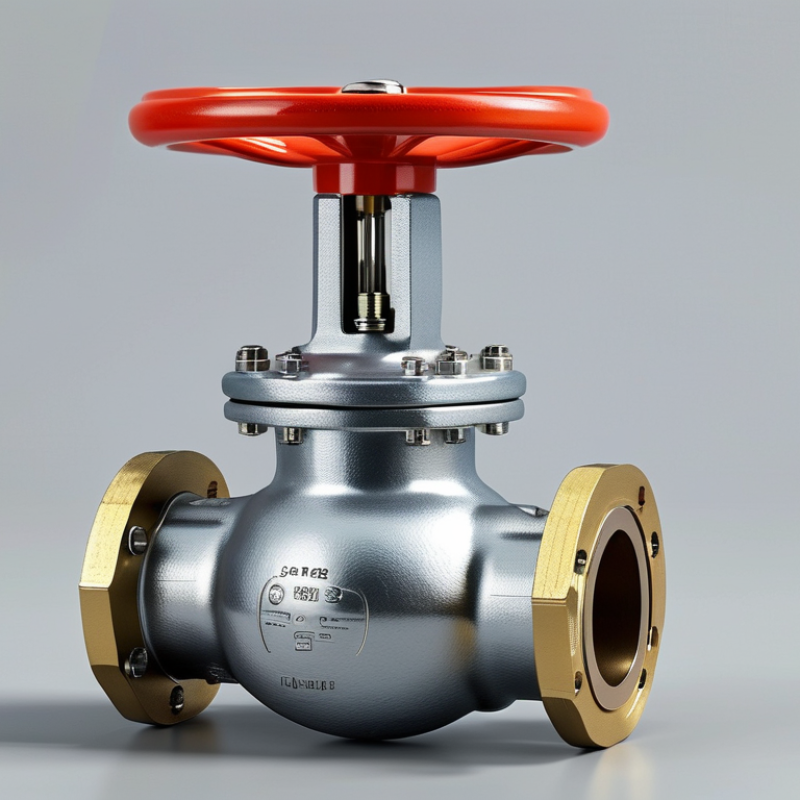
Globe Check Valve: Definition and Basic Purpose
A globe check valve is an automatic valve that permits fluid to move in one direction. Its basic purpose is preventing reverse flow after the pump stops or pressure changes. Inside, a movable disc, plug, or piston responds to pressure differences. Forward flow lifts the closure from its seat. Reverse flow pushes it firmly back.
Unlike a manually operated globe valve, it needs no handwheel or actuator. The line pressure controls its movement. This makes it useful in water, steam, chemical, and process piping systems. However, the design usually creates more resistance than a straight-through check valve. The U.S. Department of Energy identifies unnecessary pressure loss as a major pumping-system efficiency concern. That detail matters during sizing.
A globe check valve is not foolproof. Fast closure can still create water hammer. Poor installation may also cause vibration, noise, or premature seat wear. Engineers therefore review flow velocity, pressure rating, temperature, and mounting direction. ASME B16.34 provides widely used requirements for pressure-temperature ratings and valve construction. Grand View Research valued the global industrial valves market at about USD 78 billion in 2023, showing the scale of equipment involved. Yet market size does not guarantee correct selection. A valve that works well on a clean-water line may perform poorly with solids or sticky fluids. The “simple” choice deserves a second look.
Main Components and Their Functions
What Is a Globe Check Valve and How Does It Work?
A globe check valve is a one-way valve with a globe-shaped body. Its main job is preventing reverse flow in a pipeline. The valve body contains the flow passage, internal seat, and moving closure element. Strong body walls handle pressure and protect the internal parts. The seat forms the sealing surface. It must remain smooth and correctly aligned.
The disc, or piston, moves with the fluid. When inlet pressure rises, the disc lifts away from the seat. Fluid then passes through the opening. When flow slows or reverses, the disc returns to the seat. Gravity and back pressure help this movement. Some designs use a stem or guide to control disc travel. The guide reduces sideways movement and uneven wear. Small alignment errors matter.
The bonnet closes the body and allows access during maintenance. Bolts, gaskets, and seals help prevent leakage around this joint. In field inspections, technicians should check seat damage, disc scoring, and debris near the guide. A clean-looking valve can still seal poorly. Pressure readings may also mislead. The real fault might be a worn seat or restricted disc movement. Globe check valves can create noticeable pressure loss because fluid changes direction inside the body. Engineers should consider flow rate, pressure, temperature, and installation direction before selecting one. It is easy to overlook vibration. That mistake can shorten service life.
How a Globe Check Valve Operates Step by Step
What Is a Globe Check Valve and How Does It Work?
A globe check valve combines a globe-style body with an automatic non-return mechanism. It controls forward flow and limits reverse flow. The valve needs no handwheel during normal operation. Its action depends on pressure difference, not operator timing.
How a Globe Check Valve Operates Step by Step
When upstream pressure rises, fluid pushes against the disc or piston. The closure element lifts from its seat. Flow then passes through the valve’s guided passage. As velocity increases, pressure forces can create turbulence and energy loss. When upstream pressure falls, the element moves downward. Reverse flow accelerates closure. The disc seals against the seat before backflow becomes severe. It is simple, but not silent.
API 598 pressure-testing practices focus on shell strength and closure tightness. ISO 5208 also defines industrial-valve leakage testing methods. These standards do not guarantee perfect field performance. Installation direction, pipe vibration, and dirty fluid still matter. The U.S. Department of Energy reports that steam-system improvements commonly deliver 10% to 15% energy savings, although valve selection alone cannot achieve that result. This is an important distinction.
Tips: Install the valve according to the marked flow arrow. Keep the seat clean. Use a straight pipe run where practical. Check pressure drop before sizing. A valve that closes too quickly may cause water hammer. Inspect unusual noise, vibration, and temperature changes. Real systems are less tidy than drawings. Testing after installation is worth the extra effort.
Common Types and Installation Configurations
What Is a Globe Check Valve and How Does It Work?
A globe check valve is a non-return valve with a globe-shaped body and guided internal disc. It permits flow in one direction and blocks reverse flow automatically. When upstream pressure rises, the disc lifts from its seat. When flow slows, gravity or a spring returns the disc to its seat. No handwheel is required. This design provides stable closing action, but it usually creates more pressure loss than a swing check valve.
Common Types and Installation Configurations
Lift-type globe check valves suit clean liquids, steam, and gas services. Their guided disc needs a fairly straight flow path. Piston-type versions use a piston and damping effect, helping reduce sudden closure in some systems. Spring-loaded designs can install in horizontal or vertical lines, provided the arrow matches the intended flow direction. Vertical installation normally requires upward flow unless the manufacturer specifies otherwise.
Installation details matter. Keep the valve accessible for inspection and place it after pumps when reverse flow could damage rotating equipment. Use pipe supports to prevent the valve from carrying excessive mechanical load. Flush the line before installation; grit can mark the seat and cause slow leakage. I have seen a correctly sized valve fail early because the piping was misaligned. That mistake is easy to miss.
Leave enough clearance for removal. Avoid placing the valve directly beside elbows when turbulence may affect closure. Check pressure rating, temperature limits, sealing material, and minimum flow requirements against actual service conditions. In some systems, a globe check valve is not the best choice. Its reliable guidance may not justify the added pressure drop. That decision deserves careful review.
What Is a Globe Check Valve and How Does It Work? - Common Types and Installation Configurations
| Valve Type or Configuration | How It Works | Flow Direction | Recommended Installation Position | Typical Applications | Main Advantages | Key Limitations |
|---|---|---|---|---|---|---|
| Lift Check Valve | A guided disc or piston lifts from its seat when upstream pressure is sufficient and returns to the seat when flow stops or reverses. | One-way flow; the arrow on the body must point in the intended flow direction. | Usually installed in horizontal piping. Some designs are suitable for vertical upward flow when specified by the manufacturer. | Steam, water, compressed air, boiler-feed systems, and general process piping. | Fast closing action, compact flow passage, and good resistance to reverse flow when correctly selected. | Usually creates more pressure loss than a swing check valve and may require a stable flow rate to prevent disc chatter. |
| Piston Check Valve | A piston moves vertically inside a guided chamber. Line pressure raises the piston, while reverse pressure and gravity return it to the seat. | One-way flow through the valve body. | Commonly installed in horizontal lines; orientation requirements depend on the internal guide and design. | High-pressure steam, condensate, water, and process systems where controlled closing is important. | Good sealing capability and improved stability compared with an unguided disc in many services. | Higher pressure drop than some free-swinging designs; sensitive to fouling, contamination, and incorrect orientation. |
| Swing Check Valve | A hinged disc swings away from the seat during forward flow and swings back onto the seat when flow reverses. | One-way flow; installation must follow the body arrow. | Best suited to horizontal piping. Certain models allow vertical upward flow, but vertical downward flow is generally unsuitable. | Water distribution, wastewater, cooling systems, fire-protection piping, and large-diameter pipelines. | Low pressure loss at suitable flow rates and relatively simple construction. | May slam during rapid flow reversal and is not normally recommended where pulsating flow or frequent cycling occurs. |
| Tilting-Disc Check Valve | The disc pivots around an offset shaft, reducing the travel distance required for opening and closing. | One-way flow in the direction marked on the body. | Often suitable for horizontal or vertical upward-flow installation, subject to the valve design. | Large water lines, cooling-water systems, pump discharge piping, and industrial process lines. | Faster response and lower water-hammer risk than many conventional swing designs. | More complex and often more expensive than a basic swing check valve; correct flow conditions remain important. |
| Dual-Plate Check Valve | Two spring-loaded plates open into the flow path and close independently when forward flow decreases or reverses. | One-way flow; the body arrow indicates the permitted direction. | Commonly installed between flanges in horizontal or vertical upward-flow lines. Follow the manufacturer’s orientation limits. | Oil and gas systems, water treatment, HVAC, chemical processing, and pump discharge lines. | Short face-to-face length, low weight, and reduced closing travel compared with many full-disc designs. | Can be sensitive to turbulent flow, pulsation, and poor upstream piping layout; not every model is suitable for vertical downward flow. |
| Globe-Pattern Check Valve | The internal body resembles a globe-pattern valve, with a guided closing element moving toward a seat to stop reverse flow. | One-way flow through a defined inlet and outlet. | Typically installed in horizontal piping, with the flow arrow pointing toward the outlet. | Steam, hot water, boiler systems, process plants, and applications requiring guided closure. | Guided disc movement, reliable shutoff when properly selected, and suitability for high-pressure service in appropriate materials. | The tortuous flow path generally produces higher pressure loss than a straight-through check valve. |
| Pump Discharge Configuration | The check valve closes when the pump stops, helping prevent reverse flow and limiting reverse rotation of the pump. | Installed with the arrow pointing away from the pump discharge. | Usually installed downstream of the pump, with adequate straight pipe and proper support. | Water pumps, booster sets, cooling-water pumps, and process pumps. | Protects the pump and upstream equipment from reverse flow. | Incorrect sizing or slow closing can contribute to water hammer; a check valve does not replace a properly designed control system. |
| Vertical Upward-Flow Configuration | Flow rises through the valve and lifts the closing element. Gravity, a spring, or reverse pressure assists closure. | Bottom to top only unless the valve is specifically designed for another direction. | Suitable for selected lift, piston, spring-loaded, tilting-disc, and dual-plate designs. | Riser piping, pump discharge systems, water treatment plants, and vertical process lines. | Can provide dependable closure when the closing element is compatible with the vertical flow direction. | Valve type, spring force, disc weight, and minimum flow must be checked before installation. |
| Horizontal Piping Configuration | The closing element moves, swings, or pivots in response to the pressure difference between the inlet and outlet. | Flow follows the body arrow. | Suitable for most common check-valve designs, provided the manufacturer’s orientation instructions are followed. | General utility piping, industrial process lines, steam systems, and water services. | Offers broad compatibility with lift, piston, swing, globe-pattern, and wafer-style designs. | Pipe strain, misalignment, insufficient support, or nearby elbows can impair operation and increase wear. |
| Installation with Flow-Disturbing Fittings | The valve responds to pressure and velocity changes created by the piping system. Elbows, reducers, pumps, and control valves can produce turbulence. | Must follow the marked flow direction. | Install with the straight-pipe distances and orientation recommended for the selected valve. | All applications, especially high-velocity liquid, pulsating, or gas-flow systems. | Proper layout reduces disc instability, noise, vibration, and premature seat wear. | Space requirements may increase, and a poor layout can cause chatter, pressure loss, or premature failure. |
| Basic Installation and Commissioning Checks | Inspect the valve, verify the pressure and temperature ratings, confirm the flow arrow, clean the pipe, and test the system gradually. | Direction must match the intended process flow. | Install according to the valve design, piping code, and manufacturer’s instructions. | New installations, maintenance replacements, and system modifications. | Reduces the risk of leakage, incorrect operation, contamination damage, and installation-related failure. | Selection and installation should account for fluid type, flow rate, pressure, temperature, pipe size, materials, and water-hammer risk. |
Note: A check valve permits flow in one direction and automatically limits reverse flow. Exact pressure ratings, temperature limits, materials, minimum flow requirements, and allowable installation orientations vary by design standard and valve construction.
Advantages, Limitations, and Typical Applications
What Is a Globe Check Valve and How Does It Work?
A globe check valve is an automatic valve that allows fluid to move in one direction. Its rounded body contains a disc, piston, or plug that moves against a fixed seat. When inlet pressure rises, the closing element lifts and opens the passage. If flow reverses, gravity and back pressure push it onto the seat. No handwheel or actuator is normally required. In field inspections, correct flow direction matters greatly.
Advantages, Limitations, and Typical Applications
This design can provide reliable reverse-flow protection in demanding piping systems. Its guided closing element may reduce sudden movement and improve sealing performance. Globe check valves are often selected for steam, condensate, boiler feedwater, compressed air, and process lines. They suit installations where pressure and temperature remain within the specified material limits. They are not maintenance-free, though.
The main limitation is pressure loss. The fluid must change direction inside the body, creating resistance that can increase pumping costs. Incorrect sizing may also cause vibration, chatter, or damaging water hammer. Dirty fluids can wear the seat or prevent complete closure. Installation orientation must follow the valve design, especially for gravity-assisted closing. A globe check valve should not be used as a routine throttling valve. That mistake still appears in real projects. Engineers should verify pressure class, temperature range, flow velocity, maintenance access, and expected surge conditions before selection.
Related Posts
-
Maximizing Efficiency: The Advantages of Utilizing Best Ball Check Valves in Industrial Applications
-
2026 Best Ball Valve Types for Global Buyers to Consider?
-
What is a Flanged Gate Valve and Why It’s the Best Choice for Your Industrial Needs?
-
Understanding Globe Valve Types and Their Applications?
-

Unlocking Global Trade Opportunities for Gate Valve Parts at 2025 Canton Fair
-
China Top Wafer Check Valve Manufacturers and Suppliers?