
How to Choose an Ultra High Temperature Servo Motor in 2026?
Choosing an Ultra High Temperature Servo Motor in 2026 requires more than comparing torque ratings. The real decision begins with heat. A motor beside a curing oven, furnace, or aerospace test chamber may face radiant heat, limited airflow, vibration, and long duty cycles. Its label temperature is only one part of the story.
Thomas A. Lipo, a widely respected electrical-machine researcher and author, writes, “The design of electrical machines is an art as well as a science.” That idea fits high-temperature servo selection closely. Engineers must examine winding insulation, magnet stability, bearing grease, encoder limits, cable materials, and controller compatibility. Small details matter. A connector rated for 150°C may fail when its nearby cable bends repeatedly.
This guide will connect laboratory specifications with real operating conditions. It will compare continuous torque, peak torque, thermal derating, cooling methods, protection ratings, and expected service life. It will also explain why a motor rated for 200°C may not deliver full performance at that temperature. Installation distance can change the result. So can mounting metal, reflected heat, and poor ventilation.
Some choices remain uncertain. Supplier test methods are not always identical. Marketing language can also hide important limits. Therefore, buyers should request thermal maps, duty-cycle data, insulation-class details, and verified encoder ratings. The best Ultra High Temperature Servo Motor is not simply the hottest-rated model. It is the one that keeps position accurately, survives repeated thermal stress, and matches the complete machine environment.
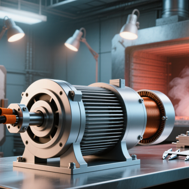
Define Ultra High Temperature Servo Motor Requirements for 2026 Applications
Defining requirements is the real starting point when choosing an ultra high temperature servo motor for 2026 applications. Record the continuous and peak temperatures at the motor housing, shaft, bearings, and feedback device. A chamber rated at 200°C may still create colder zones near the mounting flange. Measure the actual heat path.
Specify torque, speed, acceleration, positioning accuracy, and duty cycle together. A motor may reach the required peak torque but overheat during repeated indexing. State the load inertia and allowable backlash. Small details matter. Define the operating temperature range, not only the maximum temperature. Include start-up conditions, vibration, dust, pressure, and chemical exposure. These factors influence insulation, seals, lubricants, cables, and connectors.
Feedback selection deserves careful testing. Encoders and resolvers respond differently to heat, electrical noise, and long cable runs. Require verified accuracy across the full temperature cycle. Ask for derating curves, insulation data, bearing-life estimates, and test methods. Independent temperature testing is wise. Do not rely on one attractive specification sheet. A common mistake is ignoring thermal expansion between the motor and driven mechanism. That error can shift alignment and reduce repeatability. Build a prototype with real mounting hardware, then monitor winding temperature, vibration, current, and position error. Leave room for uncertainty. Field conditions are rarely perfect.
| Requirement Area | Key Specification | Practical 2026 Engineering Range | Selection Guidance for Ultra High Temperature Applications |
|---|---|---|---|
| Operating Environment | Ambient temperature at the motor housing | 150–250 °C for specialized designs; verify the continuous and short-duration limits separately. | Define the maximum measured temperature, exposure duration, heating and cooling rates, and whether the motor is operating in a furnace, vacuum chamber, autoclave, engine compartment, or other enclosed space. |
| Temperature Duty | Continuous, intermittent, and peak exposure | Continuous operation should normally be specified with a design margin of at least 10–20 °C below the qualified limit. | Do not size the motor from the peak temperature alone. Create a time-temperature duty profile and confirm winding, magnet, bearing, insulation, sensor, connector, and cable limits for every operating segment. |
| Torque | Continuous and peak torque | Specify continuous torque in N·m and peak torque with its duration, commonly 1–10 seconds depending on the motion cycle. | Include friction, acceleration, gravity, cutting or process loads, gearbox efficiency, and thermal derating. A motor that meets cold-temperature peak torque may not meet the same value at ultra-high temperature. |
| Speed | Rated speed and maximum speed | Define the complete operating range, for example 0–3,000 rpm or 0–6,000 rpm, rather than only the maximum value. | Check rotor mechanical stress, bearing speed limits, back-EMF, inverter voltage, torque weakening, and the effect of high temperature on winding resistance and available power. |
| Thermal Performance | Winding temperature and thermal class | Common insulation-system references include Class H at 180 °C and Class N at 200 °C; the complete system must be qualified, not only the wire enamel. | Use the applicable IEC 60034 requirements and obtain temperature-rise data for the assembled motor. Confirm hotspot temperature, insulation aging, thermal conductivity, and cooling conditions. |
| Cooling | Cooling method and heat rejection | Natural convection, forced air, conduction cooling, liquid cooling, or a combination may be used. | At high ambient temperature, conventional air cooling may provide limited heat rejection. Specify coolant type, inlet temperature, flow rate, pressure, allowable leakage, and the required thermal interface to the machine structure. |
| Magnetic System | Permanent-magnet temperature capability | The magnet operating limit is design-dependent; many high-temperature permanent-magnet systems require a specified limit near or above 180–200 °C. | Require reversible and irreversible demagnetization data at the maximum winding temperature and fault current. Evaluate magnetic margin, rotor retention, and torque loss after thermal cycling. |
| Feedback | Position and speed feedback | Resolvers, high-temperature encoders, or remote sensors are used according to the temperature zone and accuracy requirement. | A resolver is often preferred when the sensor is located in a hot motor area. Specify angular accuracy, repeatability, electrical interface, excitation frequency, cable length, and signal conditioning temperature limits. |
| Bearing System | Bearing type, lubricant, and life | Use high-temperature bearings, solid lubricants, or application-specific lubrication systems; standard grease should not be assumed suitable above its rated limit. | Define radial and axial loads, speed, mounting orientation, thermal expansion, preload, expected life, contamination level, and relubrication limitations. Validate bearing life at actual temperature rather than room temperature. |
| Electrical Insulation | Dielectric strength and partial discharge resistance | Specify rated voltage, inverter switching conditions, insulation-system temperature class, and required voltage withstand tests. | For fast-switching drives, assess repetitive peak voltage, common-mode voltage, corona or partial-discharge risk, creepage, clearance, and the suitability of the winding insulation for the inverter output waveform. |
| Cables and Connections | Motor leads, connectors, seals, and feedthroughs | Cable and connector temperature ratings must equal or exceed the local temperature; high-temperature fluoropolymer, mineral-insulated, ceramic, or glass-to-metal solutions may be required. | Specify conductor size, shielding, bend radius, vibration, vacuum compatibility, chemical exposure, connector mating cycles, and the temperature at both the motor end and the cooler end of the cable route. |
| Environmental Protection | Ingress, pressure, vacuum, and chemical resistance | Select the required IP rating or a separate vacuum and leak-rate specification; IP ratings alone do not define vacuum performance. | Define dust, moisture, process gases, oils, solvents, corrosive chemicals, pressure range, outgassing limits, and cleaning method. Verify seals and potting materials at the full thermal and chemical envelope. |
| Mechanical Integrity | Thermal expansion, vibration, and shock | Specify shaft, housing, and mounting materials together with dimensional tolerances across the complete temperature range. | Calculate differential expansion between shaft, bearings, housing, rotor, and driven equipment. Test resonance, balance, vibration, shock, and mounting torque after thermal cycling. |
| Drive Compatibility | Servo amplifier and control strategy | The amplifier must support the motor's phase current, bus voltage, feedback type, commutation method, and thermal derating curve. | Configure temperature-dependent current limits, over-temperature protection, stall detection, field weakening, safe torque off, and fault behavior. Confirm that feedback electronics remain within their own rated temperature range. |
| Performance Stability | Torque constant, resistance, and position accuracy over temperature | Copper resistance rises by approximately 0.393% per °C near room temperature; motor constants and control gains therefore change substantially as temperature increases. | Use temperature-compensated current control, gain scheduling, or measured parameter tables when required. Validate torque accuracy, settling time, overshoot, and repeatability at cold, nominal, and maximum temperatures. |
| Safety and Compliance | Applicable standards and risk controls | Typical references include IEC 60034 for rotating electrical machines, IEC 61800 for adjustable-speed power drive systems, and ISO 13849 or IEC 62061 where machinery functional safety applies. | Identify the legally applicable standards for the installation, document thermal and electrical hazards, provide protective earth and over-temperature protection, and complete a machine-level risk assessment. |
| Qualification Testing | Thermal cycling, endurance, and environmental validation | Test at the minimum, nominal, and maximum operating temperatures using the real load profile; include repeated thermal cycles and hot restart conditions. | Measure torque, speed, insulation resistance, dielectric withstand, feedback accuracy, vibration, noise, leakage, and demagnetization before and after testing. Include worst-case voltage, current, cooling loss, and mechanical load. |
| Documentation | Required technical data package | Motor datasheet, derating curves, temperature limits, wiring diagram, feedback data, mounting tolerances, cooling requirements, and test reports. | Require separate ratings for continuous and intermittent operation, clear reference points for temperature measurement, allowable thermal gradients, maintenance instructions, and defined acceptance criteria for the complete motor-drive system. |