

- 713.590.1312
- sale@pandbtools.com
How to Choose the Right SBMA Connector
Choosing the right Sbma Connector is not just a matter of matching a part number. A connector may fit the panel yet perform poorly if its interface, cable, or operating range does not suit the system. Small differences matter. This guide outlines practical checks, from electrical requirements to mounting and environmental conditions. It also highlights details to verify in a manufacturer’s datasheet, rather than judging by product photos or a familiar name.
Start with the system requirements: characteristic impedance, frequency range, power handling, and acceptable signal loss. Confirm the connector’s gender, coupling style, and interface dimensions against the exact mating component. Similar labels do not guarantee compatibility. They may not. Check the cable type and termination method, too. A suitable connector can become unreliable when paired with the wrong cable diameter or assembly process. Consider available mounting space, cable bend radius, and access for tightening after nearby components are installed. A bench fit can hide a field problem.
Finally, review the specified temperature range, vibration exposure, moisture conditions, and expected mating cycles. These details help determine whether the connector is appropriate for the actual installation, not just a test setup. Compare relevant performance ratings across candidate products, and ask the supplier to clarify anything the datasheet leaves uncertain. One point is easy to overlook: the best option on paper may be awkward to assemble or inspect. There is no universal best choice. The right Sbma Connector is the one that meets the system’s requirements and can be installed and verified consistently.
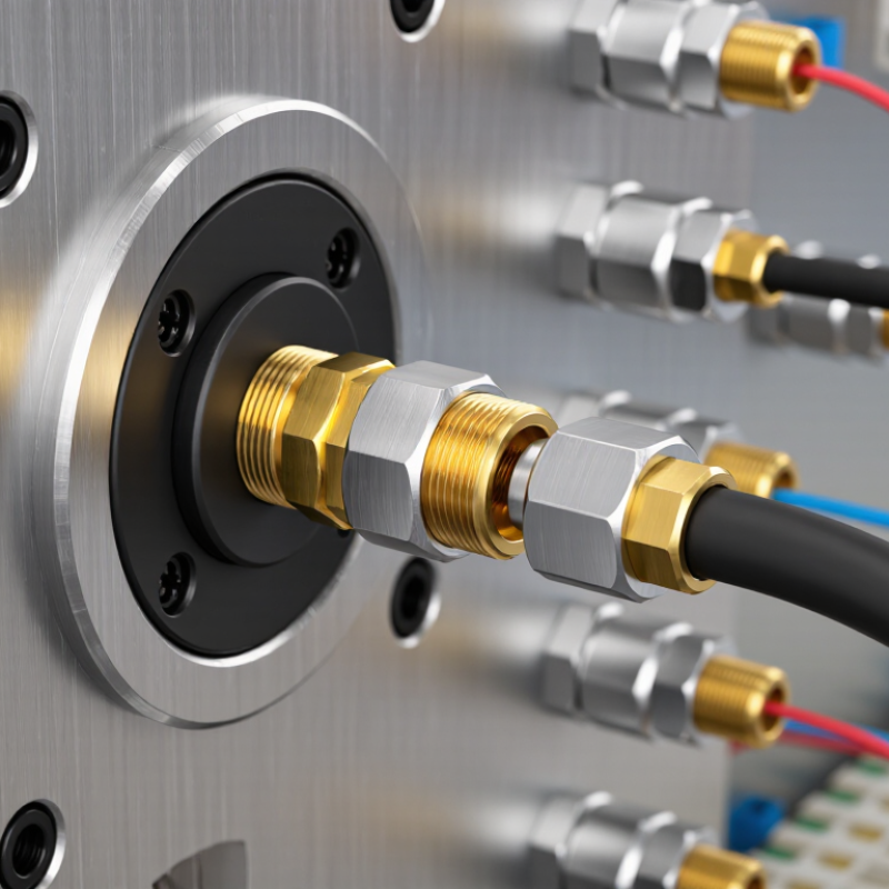
Identify the SBMA Connector’s Application and Operating Conditions
Start with the job the SBMA connector must perform. Is it joining circuit boards inside a compact module, or connecting a cable to equipment that moves? The application affects mounting style, mating access, alignment tolerance, and available space. A connector that fits a drawing may still be awkward to install or service. Small details matter. A common design mistake is choosing by size alone; that shortcut can be tempting when space is tight.
Then map the operating conditions. Compare the required frequency range, impedance, and power handling with verified specifications rather than guessing from appearance. Check the expected temperature range, vibration, shock, moisture exposure, and number of mating cycles. A connector in a stationary enclosure faces different demands from one in a portable device. Confirm cable routing and clearance, too; a sharp bend near the interface can strain the connection. Review the manufacturer’s technical data and test the assembly under realistic conditions. If the environment or duty cycle is still uncertain, record that assumption and revisit the selection before finalizing the design. Even a careful estimate can miss a practical constraint.

Determine Required Electrical and Mechanical Specifications
Choosing an SBMA connector starts with the electrical demands of the signal path, not just the catalog label. Record the operating frequency, target impedance, insertion-loss limit, return-loss limit, and required power. Check performance across the full frequency range; power handling may decrease as frequency or temperature rises. Confirm that voltage rating, shielding, and contact configuration suit the equipment. Small mismatches matter.
Mechanical fit needs the same care. Check interface dimensions, panel thickness, mounting method, and clearance behind the panel. For blind-mate installations, verify the permitted axial and radial misalignment. Do not assume the connector will absorb assembly errors. Review retention, mating-cycle rating, vibration exposure, and temperature range against the actual installation. Measure twice.
A drawing can look complete while its tolerance stack remains uncertain. Compare connector dimensions with the chassis and mating components, then confirm the limits in the current technical datasheet. If the assembly has movement or vibration, include that condition in the evaluation. A bench fit is useful, but it may not reveal what happens after repeated mating or thermal change. Check test conditions, too. A rating without its conditions is hard to apply.
How to Choose the Right SBMA Connector
Determine the required electrical and mechanical specifications before selecting a connector.
These are approximate RF band-edge references, not SBMA connector ratings; several bands overlap. Choose a connector whose datasheet covers your system’s full frequency range, then check impedance, insertion loss, and VSWR. Also confirm the required interface, mounting method, mating-cycle rating, and environmental limits for your application.
Compare Connector Types, Materials, and Mounting Options
SBMA connectors are compact, push-on RF interfaces, but matching the connector style matters. Compare plug and jack configurations, straight and right-angle bodies, and cable versus board interfaces. A straight connector may suit a tight panel layout; a right-angle version can reduce cable bend near an enclosure wall. Fit matters. Check the specified frequency range, impedance, and mating dimensions against your equipment. Do not rely on appearance alone.
Tips:
Confirm whether the assembly needs a PCB mount, cable termination, or bulkhead mount. For circuit boards, surface-mount parts save space, while through-hole styles can provide firmer mechanical support. Measure available clearance before ordering. Small detail.
Materials affect durability and signal consistency. Connector bodies may use brass or stainless steel, while contact finishes and insulators vary by design. Choose materials suited to expected mating cycles, vibration, and operating conditions; a tougher body is not automatically the best fit. Review the manufacturer’s data sheet for plating, temperature limits, and recommended assembly methods. If the installation is cramped, sketch the connector and cable path at full scale. I have seen a technically suitable part become awkward once the lid was fitted. Check twice.
Check Compatibility with Cables and Connected Equipment
Before choosing an SBMA connector, identify the cable’s exact type, impedance, and outer diameter. The connector must match the cable construction, not just its apparent size. Check the cable datasheet for conductor dimensions, dielectric material, and jacket limits. A close fit can still create poor contact or damage during assembly. Measure twice.
Next, compare the connector’s mating interface with the port on the connected equipment. Confirm the interface designation, contact arrangement, and coupling method in both sets of documentation. Similar-looking interfaces are not necessarily interchangeable. Check operating frequency, impedance, and power ratings across the connector, cable, and equipment; the lowest-rated part may limit the entire path. Small details matter.
Also consider how the cable will sit once connected. Verify port orientation and clearance, especially where equipment is mounted in a tight enclosure. An adapter can resolve a mismatch, but it adds another connection and may affect signal loss or mechanical stability. Avoid sharp bends close to the connector, and follow the specified assembly method rather than forcing a connection that feels tight. If the cable specification or port details are unclear, pause and confirm them before ordering; visual inspection alone can be misleading.
Evaluate Reliability, Standards, and Supplier Quality
How to Choose the Right SBMA Connector
Evaluate Reliability, Standards, and Supplier Quality
A dependable SBMA connector should match the electrical and mechanical needs of the equipment. Check its interface, impedance, frequency range, and rated performance against the system design. Small mismatches matter. At the bench, inspect the coupling surfaces and center contact for burrs, uneven plating, or looseness. These details can affect repeatability, especially when connectors are mated often or installed in tight spaces.
Standards help make specifications comparable, but a reference on a datasheet is not proof of compliance. Confirm which interface and test requirements apply, then request current test reports or documented inspection results. Look for measured insertion loss, voltage standing wave ratio, and durability data across the intended frequency range. One easy mistake is trusting a single best-case figure too much. Ask how performance varies between samples and production lots.
Supplier quality matters as much as the connector drawing. Request material and plating specifications, lot traceability, and clear acceptance criteria. A capable supplier should explain how dimensions are inspected and how failed parts are handled. Evaluate samples in the actual assembly, not only on a test bench; cable routing and mounting pressure can change results. Keep records of the parts tested. It is easy to skip that step when schedules get tight.