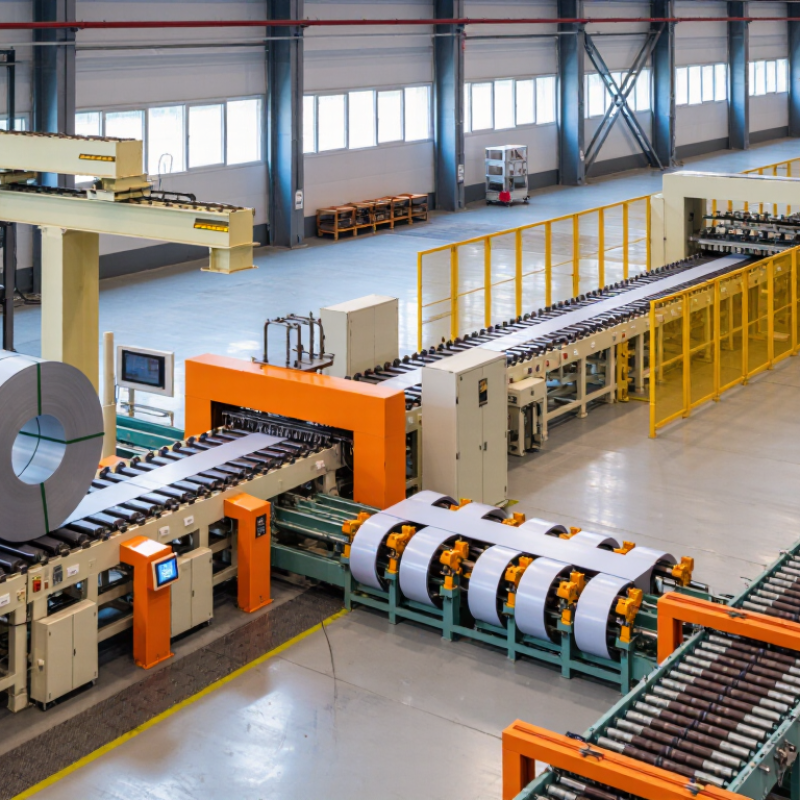
2026 Best Transformer Core Cutting Line for Global Buyers?

Choosing the 2026 best Transformer Core Cutting Line is not simply a matter of selecting the fastest machine. Global buyers must examine accuracy, stability, service support, energy use, and long-term production evidence. A modern line may include automatic decoiling, precision slitting, step-lap stacking, scrap control, and digital monitoring. Yet these features matter only when they perform consistently on the buyer’s actual steel grades and core sizes.

Martin J. Heathcote, a respected transformer engineering author, wrote, “A transformer is a static device.” This short observation remains important. The transformer does not move during operation, but its magnetic performance depends heavily on manufacturing precision. A small burr, uneven strip width, or incorrect step-lap position can increase losses and noise. Details matter.

Real factory experience should guide the decision. Buyers should request sample-cut results, burr measurements, stacking photographs, cycle-time records, and references from comparable plants. Supplier claims deserve verification. A polished brochure is not production evidence. Not every “smart” line improves output. Sometimes, simpler controls prove more reliable for operators and maintenance teams.

This guide compares leading Transformer Core Cutting Line solutions for international buyers in 2026. It considers electrical steel handling, cutting tolerance, automation depth, operator training, spare-parts access, and after-sales response. Regional standards and site conditions also require attention. A line designed for one market may need adjustments elsewhere. No machine is perfect. That is worth remembering. The best investment balances measurable performance, practical usability, and dependable support over many production years.

2026 Best Transformer Core Cutting Line for Global Buyers?

2026 Transformer Core Cutting Lines: 50/60 Hz and IEC 60076 Requirements

Transformer demand is rising with grid expansion and renewable integration. The IEA’s Electricity 2024 report forecasts global electricity demand growth of 3.2% annually through 2026. This growth increases pressure on manufacturers to produce efficient cores consistently.

A 2026 transformer core cutting line should support both 50 Hz and 60 Hz designs. Frequency changes influence magnetic flux density, losses, and core dimensions. Grain-oriented electrical steel requires accurate slitting, step-lap cutting, and controlled stacking. Burrs, edge damage, and incorrect angles can increase no-load losses. IEC 60076 defines important transformer performance requirements, including temperature rise, insulation, losses, and testing. It does not prescribe one cutting-line layout. Buyers must connect the line’s accuracy with the finished transformer’s test results. This distinction is often missed.

Tips: Request verified data for cutting accuracy, burr height, scrap rate, and stacking-factor stability. Ask for sample production using your actual steel grades. A practical line should handle different widths without excessive setup time. Automation helps, but it cannot replace operator judgment. I have seen specifications look excellent on paper, yet unstable feeding caused uneven laminations. That weakness deserves honest review. Also compare service response, spare-part availability, and training plans across regions. The IEA’s Electricity Grids and Secure Energy Transitions report estimates that grid investment must accelerate sharply by 2030, making dependable production equipment increasingly important.

Electrical Steel Standards: 0.23–0.30 mm GO Steel and ASTM A677

A transformer core cutting line must handle 0.23–0.30 mm grain-oriented electrical steel with controlled tension and clean slitting. Thin laminations reduce eddy-current losses, but they also punish poor alignment. A small burr can damage insulation and increase local heating. Small details matter.

Buyers should read ASTM A677 carefully. ASTM A677/A677M generally covers fully processed non-oriented electrical steel, so it should not automatically define grain-oriented steel for transformer cores. For GO steel, confirm the applicable material standard, magnetic properties, thickness tolerance, coating quality, and core-loss values with the mill and testing laboratory. Do not rely only on a supplier’s certificate. Check samples.

A reliable cutting line should maintain accurate step-lap lengths, stable stacking, and repeatable angle control. Operators should inspect strip edges, punching marks, burr height, and lamination count during production. A clean workshop also protects the coating from dust and metal fragments. Measure twice.

In practical purchasing, request trial-cut results using the actual 0.23–0.30 mm material. Review core-loss data before and after cutting. The figures may differ. This is where many plans become too optimistic. Cutting speed is useful, but excessive speed can reduce accuracy and raise waste. A balanced specification should include tolerance records, calibration procedures, operator training, and traceable inspection reports.

Cutting Methods Compared: Slitting, Shearing, and Step-Lap Accuracy

2026 Best Transformer Core Cutting Line for Global Buyers?

Choosing a transformer core cutting line starts with the steel grade, core design, and required production volume. Slitting divides wide electrical steel into narrow strips with consistent width. It suits regular strip production and high material utilization. However, poor tension control can create burrs, camber, or unstable coil edges.

Shearing cuts individual laminations to fixed lengths. It works well for straightforward core shapes and flexible production schedules. Step-lap cutting adds precise offsets between laminations, reducing air gaps and improving magnetic performance. In my experience, step-lap accuracy depends on servo response, blade condition, and operator adjustment. A line may claim tight tolerance, yet real results can change after long shifts. That detail is easy to overlook.

Tips: Ask for test cutting with your actual electrical steel. Measure burr height, strip width, cut angle, and step-lap offset. Check samples after continuous running, not only during a short demonstration. Inspect the control interface, coil loading process, and scrap collection area. Operators need clear access and practical training. One small setup error can waste expensive material. Also, request maintenance records and calibration procedures. These documents reveal more than polished specifications. No line is perfect. Build a tolerance review into your purchasing plan.

2026 Best Transformer Core Cutting Line for Global Buyers? - Cutting Methods Compared: Slitting, Shearing, and Step-Lap Accuracy
Evaluation Dimension Slitting Method Shearing Method Step-Lap Cutting Line Buyer Relevance in 2026
Primary function Cuts wide electrical-steel coils into narrower strips using rotary knives. Cuts individual laminations to length with a guillotine or flying shear. Cuts and stacks transformer laminations with programmed step-lap offsets. The best configuration depends on whether the priority is coil preparation, lamination production, or finished-core performance.
Typical material Grain-oriented electrical steel and non-oriented electrical steel supplied in coils. Electrical-steel strips or sheets after slitting, generally within the machine’s specified thickness range. Grain-oriented electrical steel used for distribution and power transformer cores. Material grade, coating, thickness, and rolling direction must be matched to the core design.
Common thickness range Approximately 0.15–0.35 mm for many transformer-grade electrical-steel applications. Approximately 0.15–0.35 mm, subject to blade clearance, material strength, and equipment design. Commonly approximately 0.20–0.35 mm, with thinner grades requiring tighter process control. Request verified processing capability for the exact steel grade and thickness rather than relying on a general range.
Typical strip or cut-width capability Multiple narrow strips from one coil; practical minimum width depends on knife diameter, material, and line design. Cuts the full strip or selected widths to the programmed lamination length. Configured for core-leg and yoke widths; width capability is determined by the line layout and tooling. Confirm usable width, minimum scrap edge, maximum coil width, and the number of slitting lanes.
Cut-length accuracy Not the primary function; length is normally controlled downstream during cut-to-length processing. Often specified around ±0.10–0.20 mm under stable operating conditions; actual accuracy is machine- and material-dependent. Often specified around ±0.10–0.20 mm for lamination length, subject to calibration and production speed. Require sample measurements across the full working width and at both low and high production speeds.
Width accuracy Commonly controlled in the range of approximately ±0.05–0.10 mm with properly set rotary knives. Usually depends on incoming strip width; the shearing operation primarily controls length and edge quality. Typically relies on accurate slitting and guide alignment; approximately ±0.05–0.10 mm is a common target range. Width variation directly affects joint alignment, stacking quality, and magnetic performance.
Step-lap offset accuracy Not applicable unless integrated with a dedicated step-lap cutting and stacking system. Not applicable as a standalone shearing operation. Commonly controlled to approximately ±0.10–0.20 mm, depending on servo resolution, sensing, and setup. Step-lap precision is a key purchasing criterion because it influences joint area, loss, noise, and stacking consistency.
Edge quality Clean edges are achievable, but burrs increase when knife clearance, overlap, or blade condition is incorrect. Produces a sheared edge; excessive burr, rollover, or deformation can result from incorrect clearance or worn tooling. Combines slitting and shearing quality requirements; edge damage must be minimized to protect magnetic performance. Set a measurable burr limit and inspect edges at regular intervals during acceptance testing.
Production speed Generally high for continuous coil processing; speed is limited by coil weight, strip width, tension stability, and burr control. Suitable for repeated cut-to-length production; output depends on stroke rate, lamination length, and stacking method. Usually lower than basic slitting because cutting, positioning, step-lap sequencing, and stacking occur in one coordinated process. Compare usable output, not only maximum line speed; include setup time, scrap, and quality interruptions.
Automation level Can include automatic tension control, edge guiding, strip tracking, scrap winding, and recipe management. Can include automatic length setting, flying shear control, stacking, counting, and fault monitoring. Typically integrates servo drives, automatic step-lap programming, lamination counting, stacking control, and data logging. For global operations, prioritize recipe traceability, remote diagnostics, alarms, and multilingual operator interfaces.
Material utilization Can achieve strong coil utilization when strip-width nesting and scrap recovery are carefully planned. End trim and cut-length scrap depend on the nesting plan and the transformer core design. Optimizes core geometry, but step-lap patterns and end cuts create design-dependent scrap. Evaluate scrap percentage by actual core schedule rather than by a single nominal part.
Best-fit applications Coil preparation, strip production, and operations supplying several downstream core sizes. Straight-cut laminations, prototypes, smaller production batches, and lines where flexible length changes are important. High-efficiency distribution and power transformer cores requiring controlled step-lap joints. Choose based on annual volume, core design, required loss level, and labor availability.
Main maintenance priorities Knife sharpness, knife overlap, clearance, tension rollers, edge guides, and scrap-winding equipment. Blade condition, shear clearance, slide alignment, encoder calibration, and material support. All slitting and shearing items plus servo calibration, sensors, stacker alignment, and step-lap tooling. A preventive-maintenance schedule is essential for maintaining repeatable accuracy over long production runs.
Overall selection profile Best for flexible, high-throughput coil conversion and accurate strip-width production. Best for straightforward cut-to-length work, flexible product changes, and controlled initial investment. Best for integrated, high-accuracy transformer-core production where joint quality and repeatability are priorities. For most advanced transformer-core projects, compare the complete line, tooling, stacking system, commissioning, and acceptance-test results.
Technical note: The accuracy figures shown are typical target ranges for properly configured equipment and stable production conditions. Final values should be confirmed through a documented factory acceptance test using the buyer’s specified electrical steel, thickness, width, cutting pattern, and production speed.

Key Performance Data: ±0.1 mm Length Tolerance and Burr Control

Global transformer demand is rising with grid expansion and renewable integration. The International Energy Agency’s Electricity 2024 report projects global electricity demand to grow by more than 3% annually through 2026. This pressure reaches the core-cutting floor. A cutting line must hold a ±0.1 mm length tolerance across repeated batches, not only during a short factory trial.

That tolerance protects step-lap geometry and reduces unwanted air gaps between laminations. Even a small length error can increase assembly adjustments and local magnetic losses. IEC 60404-8-7 defines requirements for grain-oriented electrical steel used in magnetic circuits. Buyers should request measured results, not attractive brochures. Review sampling frequency, gauge calibration, coil width variation, and temperature conditions. Details matter.

Burr control deserves equal attention. Excessive burrs can damage insulation coatings, disturb stacking pressure, and raise the risk of interlaminar current paths. ASTM A876/A876M provides relevant requirements for grain-oriented electrical steel products, but it does not replace line-specific inspection. Ask for burr-height data at both edges and after extended production. Short tests can mislead. In practice, a stable line should record cutting speed, tool wear, scrap rate, and tolerance drift together. The difficult part is consistency. A ±0.1 mm result may appear excellent, yet poor maintenance can quickly weaken it. Buyers should also inspect sample cores by touch and microscope, because numerical records alone can miss sharp, uneven edges.

The reference profile shows how cutting speed can influence dimensional accuracy and burr height in transformer core processing. The target envelope is an absolute length deviation of no more than ±0.10 mm, with burr height controlled to approximately 30 μm or less. Actual acceptance values should be confirmed against the buyer’s drawing, material grade, and process specification.

Global Buyer Checklist: ISO 9001, CE, Throughput, and Service Support

Choosing the best transformer core cutting line in 2026 requires more than comparing cutting speed. The IEA Electricity 2024 report projected global electricity demand growth of about 4% in 2024 and 2025. That pressure increases demand for efficient transformer production. Buyers should examine actual throughput, not brochure capacity. Ask for verified figures at the required silicon-steel width, thickness, and stacking pattern. Request test samples. Inspect burr height, kerf accuracy, scrap rate, and automatic stacking stability.

Quality evidence matters. The ISO Survey 2023 recorded more than one million ISO 9001 certificates worldwide, but a certificate alone proves little. Check the issuing body, validity, factory address, and certification scope. The scope should cover transformer core processing or relevant manufacturing activities. CE compliance also requires careful review. Request the EU Declaration of Conformity, applicable standards, risk assessment records, and electrical safety documentation. CE is not simply a marketing certificate.

Service support can decide production continuity. Clarify installation training, remote diagnostics, spare-parts availability, and response times in writing. Ask whether technicians can support your time zone. A practical acceptance test should run several coils, not one perfect sample. High speed can hide unstable stacking. I would also question promised uptime without maintenance records. A slower line with stable accuracy may deliver better annual output. Leave room for operator feedback; real factories rarely behave like demonstrations.

REQUEST A QUOTE

Menu
[all-fields]